 EN
EN

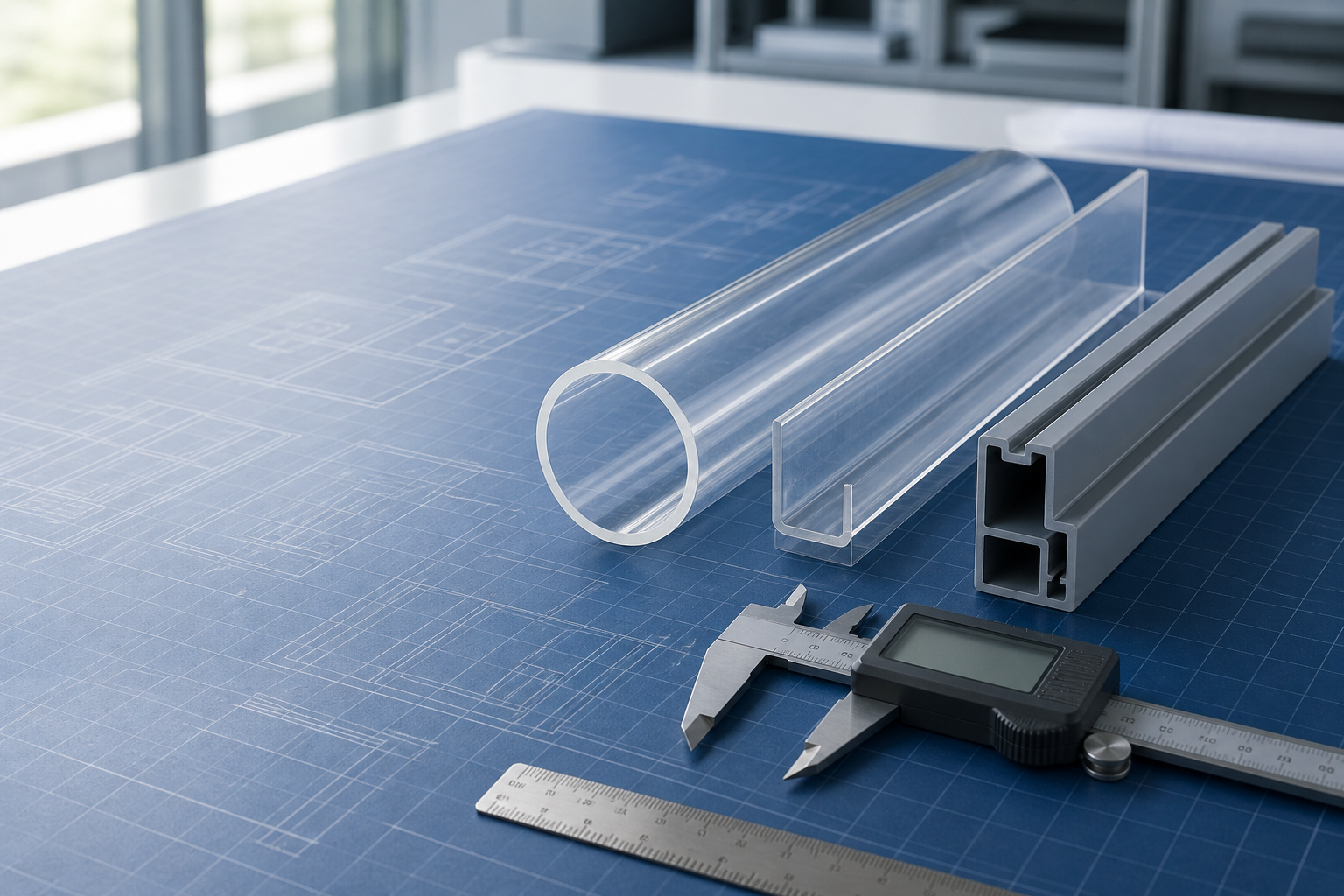
Mastering Custom Plastic Extrusion Tolerances: The DIN 16941 Standard
A definitive engineering analysis of dimensional control, material-specific shrinkage, and achievable limits in high-precision profile manufacturing.
Unlike injection moulding, where molten plastic is packed into a rigid closed steel cavity, plastic extrusion is a continuous, dynamic process. Semi-molten polymer is forced through a steel die, calibrated in a vacuum sizing chamber, cooled in a water bath, and pulled by a caterpuller. Because the material undergoes volumetric shrinkage and thermal transition while moving, achieving absolute dimensional perfection is physically impossible.
To establish a consistent, reliable basis for B2B procurement and quality assurance, the European and global extrusion industries rely primarily on the DIN 16941 standard. This guide breaks down the precise tolerance values defined by DIN 16941 and provides engineering insights into how material selection, tooling design, and cooling technologies influence the final dimensions of custom extruded profiles.
1. The DIN 16941 Standard Tolerance Guide
Unless custom tolerances are explicitly negotiated and stated on the engineering drawings, a professional extrusion factory will default to the general tolerances of DIN 16941-2A and 2B. The tables below outline the limit values across nominal ranges for width, thickness, and height dimensions.
Width Dimension Tolerances
Width refers to the horizontal cross-sectional span of the profile. Standard tolerances are sufficient for most structural enclosures, but special calibration is available for critical interfaces.
| Nominal Dimension Range (mm) | DIN 16941-2A / 2B Standard Tolerance (mm) | High-Precision Sizing Capability (mm) |
|---|---|---|
| 0 to 3.0 | ± 0.30 mm | ± 0.10 mm |
| > 3.0 to 6.0 | ± 0.40 mm | ± 0.15 mm |
| > 6.0 to 10.0 | ± 0.50 mm | ± 0.15 mm |
| > 10.0 to 18.0 | ± 0.60 mm | ± 0.20 mm |
| > 18.0 to 30.0 | ± 0.70 mm | ± 0.20 mm |
| > 30.0 to 50.0 | ± 0.80 mm | ± 0.30 mm |
| > 50.0 to 80.0 | ± 1.00 mm | ± 0.40 mm |
| > 80.0 to 120.0 | ± 1.20 mm | ± 0.60 mm |
| > 120.0 to 180.0 | ± 1.40 mm | ± 0.70 mm |
| > 180.0 to 250.0 | ± 1.70 mm | ± 0.80 mm |
| > 250.0 to 320.0 | ± 2.00 mm | ± 1.00 mm |
| > 320.0 | ± 0.8% of dimension | ± 0.4% of dimension |
Wall Thickness Dimension Tolerances
Wall thickness consistency is critical in extrusion, particularly for optical lighting profiles (where uneven walls cause light refraction hotspots) and structural tubes. DIN 16941 limits are tighter for thickness dimensions to prevent structural weak points.
| Nominal Thickness Range (mm) | DIN 16941-2A / 2B Standard Tolerance (mm) | Process Optimization Limit (mm) |
|---|---|---|
| < 1.20 mm | ± 0.20 mm | ± 0.08 mm |
| > 1.20 to 2.50 mm | ± 0.30 mm | ± 0.12 mm |
| > 2.50 to 4.00 mm | ± 0.40 mm | ± 0.15 mm |
| > 4.00 to 6.50 mm | ± 0.50 mm | ± 0.20 mm |
| > 6.50 to 10.00 mm | ± 0.60 mm | ± 0.25 mm |
| > 10.00 mm | ± 8.0% of dimension | ± 4.0% of dimension |
Height Dimension Tolerances
Height tolerances govern the vertical dimensions of flanges, channels, and ribs in custom profiles. They track closely with width limits but account for independent vertical die swell.
| Nominal Height Range (mm) | DIN 16941-2A / 2B Standard Tolerance (mm) | High-Precision Limit (mm) |
|---|---|---|
| 1.0 to 6.0 mm | ± 0.30 mm | ± 0.12 mm |
| > 6.0 to 10.0 mm | ± 0.40 mm | ± 0.15 mm |
| > 10.0 to 18.0 mm | ± 0.60 mm | ± 0.20 mm |
| > 18.0 to 30.0 mm | ± 0.80 mm | ± 0.30 mm |
| > 30.0 to 50.0 mm | ± 1.00 mm | ± 0.40 mm |
| > 50.0 to 80.0 mm | ± 1.40 mm | ± 0.50 mm |
| > 80.0 to 120.0 mm | ± 1.80 mm | ± 0.70 mm |
| > 120.0 to 180.0 mm | ± 2.50 mm | ± 1.00 mm |
2. Material Physics: Why Tolerance Achievability Differs by Resin
Every polymer behaves uniquely when transitioned from an amorphous molten state back into its crystalline or glass-like solid form. The inherent shrinkage rate of the resin is the primary material-level driver of dimensional variation.
PC & PMMA (Amorphous Rigid)
Polycarbonate (PC) and Acrylic (PMMA) have excellent dimensional stability. They exhibit relatively low mould/die shrinkage (typically 0.5% to 0.7%). This low shrinkage allows experienced factories to easily exceed standard DIN 16941 limits, achieving high-precision tolerances on optical diffuser profiles and protective tubes through precise vacuum calibration.
Rigid PVC & ABS
Rigid PVC and ABS exhibit consistent, predictable flow characteristics. PVC is highly rigid, holds shape extremely well immediately after exiting the die, and has low thermal shrinkage. ABS has excellent impact toughness and maintains its profile geometry with minimal post-extrusion warping.
PP & PE (Semi-Crystalline)
Polypropylene (PP) and Polyethylene (PE) are semi-crystalline polymers. As they cool, polymer chains organize into dense, ordered structures, causing massive volumetric shrinkage (often 1.5% to 3.0%). This high shrinkage rate makes holding tight tolerances incredibly challenging. It requires precise temperature zoning in the cooling bath to prevent asymmetrical twisting.
TPU & Soft PVC (Elastomers)
Flexible polymers (TPU and Soft PVC) are highly elastic. When exiting the die, they are susceptible to pull-induced stretching and gravity-induced sagging. Controlling cross-sectional dimensions on flexible extrusions requires slow extrusion speeds, customized interior support mandrels, and extremely stable pulling tension.
3. Advanced Manufacturing Controls for High-Precision Extrusions
When custom applications require high-precision tolerances that are tighter than standard DIN 16941 limits, manufacturing engineers must implement specialized in-line process controls and design optimizations:
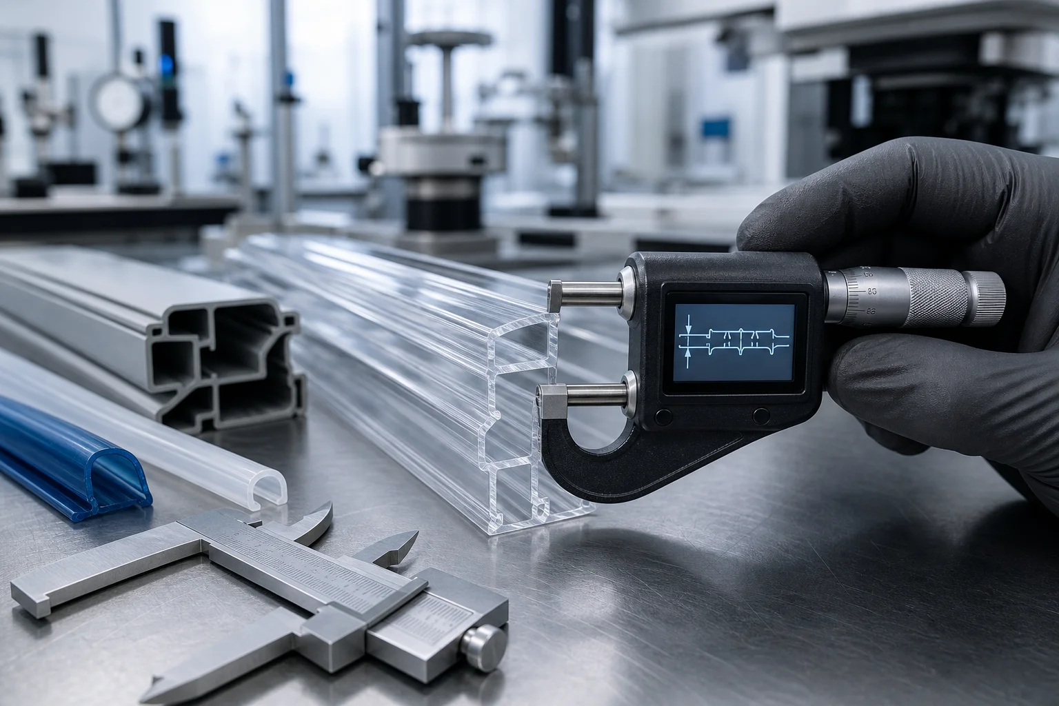
- In-Line Laser Calipers and Monitoring: Dual-axis or triple-axis laser calipers continuously measure outer dimensions as the profile exits the cooling tank. These calipers feed real-time dimensional data back to the caterpuller to adjust pull speed dynamically.
- Precision Vacuum Calibration: Unlike open-water cooling, vacuum sizing tanks pull the semi-molten outer walls of the profile firmly against a high-precision, cooled brass or stainless-steel calibrator sleeve, freezing the exterior dimensions before significant shrinkage can occur.
- In-House Tooling and Die Optimization: Extrusion die design must compensate for "die swell"—the physical expansion of polymer as it exits pressure constraints. Designing tooling in-house allows rapid prototype testing and EDM wire-cutting refinement of the steel die to match the exact swelling index of specific polymer batches.
- Balanced Wall Thickness Design: Custom profiles with adjacent thick and thin sections cool unevenly, leading to sinking and warping. Keeping wall thicknesses as uniform as possible allows the material to cool at the same rate, naturally minimizing dimensional variation.
4. B2B Sourcing Advice: Specify Wisely to Control Project Costs
For custom profile procurement, tighter is not always better. Specifying tolerances that are needlessly strict can significantly increase project costs and delay development. Here are three practical tips for procurement managers:
- Over-tolerancing drives up tooling costs: Requesting ±0.05 mm on non-functional dimensions forces the tooling engineers to design highly complex calibrators, slows production speed, and increases scrap rates, leading to higher unit costs.
- Define fit-and-function regions: Clearly mark critical assembly interfaces or sliding tracks on your drawings. A factory can then focus its precision calibration fixtures on those specific dimensions while allowing standard DIN 16941 limits on secondary cosmetic regions.
- Verify with pre-production samples: Always request initial extrusion samples from the first tooling trial. Assemble these samples in the real-world environment to confirm fit before authorizing mass production. It is much easier to adjust a steel extrusion die than to modify finished parts.
The standard limit values presented in this guide are derived from the official DIN 16941 (Thermoplastics extruded profiles - General tolerances of size, form, and orientation) specification. Real-world tolerances remain highly dependent on the chosen polymer grade, wall thickness balance, profile shape complexity, and overall cross-sectional area. Always consult with our technical engineering team before finalizing custom product specifications.
Have a Project with Strict Tolerance Requirements?
Send us your custom profile CAD drawings, material selection, and assembly requirements. Our technical tooling engineers will analyze your design, recommend optimal tolerances, and design custom in-house tooling to ensure a perfect fit.
Request a Technical Feasibility Review